Leo Wang

About
Experiences
Skills
School
Face Tracker
Jan 2026 -
This is a pan-tilt face-tracking camera.
Hardware Prototype (Completed)
Built a prototype integrating:
- A V4L camera
- A NEMA 17 stepper motor
- A temporary microcontroller
- Power supply and control circuitry
3D modeled the camera base to assess physical constraints and define dimensions for the custom PCB. Also tested the motor under heavy load and rapid switching commands to assess current threshold (for the PCB).
Control and Tuning (Completed)
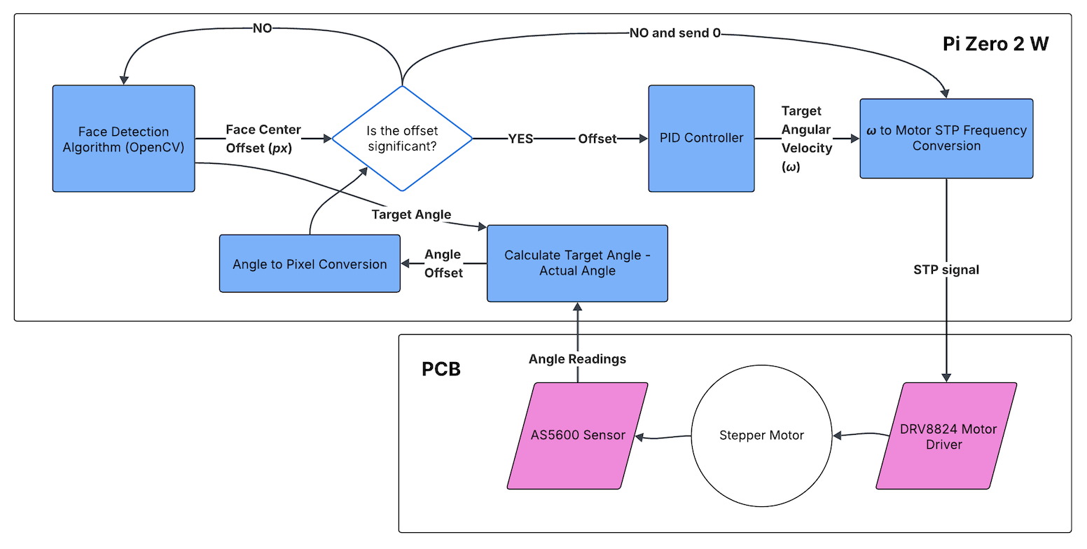
The face detection algorithm was written in Python using OpenCV and it was verified on my computer. For simplicity, the motor control logic was initially written and tested on a STM32 dev board. Later, it was adapted into Python. Both programs are now stored on a Raspberry Pi Zero 2W which serves as the processor of the project.
Programming was done using SSH and VSCode.
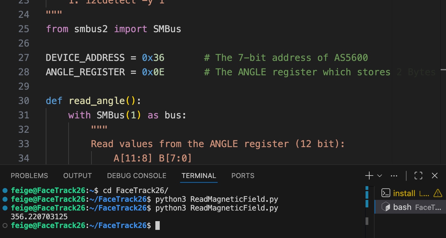
I’m using a closed-loop PID controller to actively drive the motor, with the target PWM driving frequency adjusted based on the angle offset provided by the onboard magnetic encoder via I2C.
The PID parameters were physcially tuned using a custom 3D base.
ROS2 Integration (In Progress)
Camera motion in one axis is relatively simple to control, however, with the addition of the second motor, the program must continuously switch between reading the angle, updating each motor with the new position, and checking whether the person has moved. It’s going to be impossible to navigate if we add new functions such as checking the PCB temperature or enabling voice commands. As a result, I’m adding ROS2 to this project. In addition to the reasons mentioned above, I’m also doing this because I wanted to have a STM32 chip on the PCB, and it will be much easier to communicate with it using C.
PCB Design (In Progress)
I’m using a DRV8825 motor driver for the motors, but the board uses a potentiometer for current limiting and male header pins for communication, which are not reliable for long term use.
In addition, I need to power both the Pi and the motors, so I will need a proper power distribution solution. With that in mind, I plan to move to a custom 4-layer PCB design once PID tuning and ROS2 are integrated into the system.